CHS
CHS Walsun Mall
Support

 Knowledge Base +
  2024.02.23
As shown in Figure 1, in the coherent optical module, at the transmitter side, the customer then the electrical signal through the digital signal processing function in the DSP chip to complete the specific probability distribution and QAM mapping of the symbols, which includes the probability distribution matching, FEC coding, QAM mapping, and other functions, and then the digital QAM signal of the baseband signal signal spectral shaping and the transmitter side of the pre-compensation process in order to make up for the undesirable characteristics of the optoelectronic device.

Figure 1. Functional schematic of coherent optical module (single disk)
After these DSP processing, it is fed into the four-channel high-speed DAC, which is converted into a high-speed analog bandwidth electrical signal through digital-to-analog conversion. After amplification by the driver loaded to the polarization multiplexing optical IQ modulator to complete the up-conversion, the baseband electrical signals loaded to the amplitude of the optical carrier, phase and two orthogonal polarization state, by the optical amplifier/attenuator inside the optical module for optical power control and then output, that is, the resulting high-speed optical signals.
At the receiving end, the high-speed optical signal after ICR in the role of the local oscillator light coherent mixing and photoelectric conversion to get the baseband electrical signals, and then through the high-speed ADC sampling, the realization of the electrical signal digitization, and then with the help of the receiving end of the powerful DSP equalization capabilities of the signal in the line and optical transceiver module to compensate for the damage experienced by the damage. The DSP processing flow at the receiving end includes resampling, optical front-end compensation, dispersion compensation, clock recovery, polarization demultiplexing adaptive equalization, frequency deviation estimation, phase recovery, constellation diagram demapping, and FEC decoding in sequence.
The linear IQ modulation and coherent detection of the optical field make the receiver theoretically able to recover all the optical field information of the optical signal, and the DSP processing is able to perfectly compensate for the linear impairments that the optical signal undergoes, such as inter-channel skew, IQ amplitude and phase imbalance, optical fiber Chromaticity Dispersion (CD) and Polarization Mode Dispersion (PMD), Frequency Bias, and Phase Noise, etc., and even through the special algorithmic design, it can also The high performance SD-FEC algorithm in the 800G coherent DSP chip has better error correction capability than the HD-FEC in the earlier 100G DSP chip, which further improves the OSNR tolerance of the signal and ensures error-free transmission in suitable application scenarios. Transmission.
Further, on the internal or external single disk of the optical module, through the Gearbox or Framer chip, the line-side electrical signals and the customer-side electrical signals are interfaced to accomplish different functions, such as transponder and muxponder. Of course, the optical module also needs some other auxiliary chips, such as power supply chip, clock chip and FPGA control chip and temperature monitoring chip. In addition, the DSP chip should also have SerDes function in order to better interconnect with the customer side signal.
In general, the core chip in the coherent optical module can be divided into two categories: optical chip, including double bias IQ modulation, lasers, coherent optical mixer, balanced detector; electrical chip, including modulator driver (driver), transimpedance amplifier (TIA), DSP chip. From the chip manufacturing technology, now the electric drive are based on Si or SiGe materials with CMOS standard process, the core part of the DSP chip due to power consumption and performance requirements, the need to use more advanced 7nm node process.
_1708658158.png "640 (1)_1708658158.png")
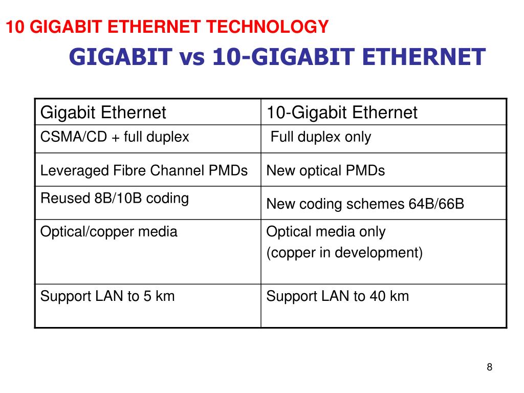
Table 1, based on different materials to make different devices performance comparison
Optical chips can be divided into two categories, one is based on III-V materials such as InP, including lasers, modulators, detectors (GaAs). The second is based on Si-based, including Si-based modulators, coherent receivers and so on. Although in recent years with the device integration and co-packaging requirements, SiP has become a hot academic and industrial favorite, but essentially for coherent optical modules, InP vs SiP who is good and who is bad is not conclusive. In general, both have their own strengths, as shown in Table 1. InP platforms are better at active devices, while SiP performs better at passive devices. SiP has an advantage in yield and cost, but may not be as good as InP in terms of bandwidth and performance.
InP platforms can integrate/co-package lasers with CDMs and ICRs, while SiP can integrate/co-package DSPs with PICs without lasers.SiP has a lot of advantages, but its non-negligible drawbacks are twofold: firstly, it is coupled with optical fiber with high loss, and secondly, it cannot emit light by itself (LEDs recently made by Dr. MIT are still too early to be used in practical optical communication applications). Instead of saying who replaces who, there are times when it may be necessary to consider how to combine the advantages of both, such as Si+X, hybrid integration, so that both cost and performance are optimized as much as possible.
Subscribe to the newsletter
for all the latest updates.


2-5# Building, Tongfuyu Industrial Zone, Aiqun Road, Shiyan Street, Baoan District, Shenzhen. China